Honda F1 Engine Secrets Revealed: Inside the Groundbreaking Technology and Innovations
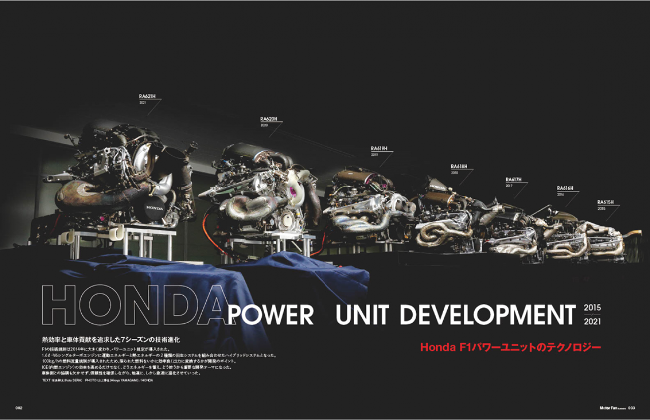
The technical regulations in F1 underwent a significant change in 2014. Honda's power unit had evolved steadily yet rapidly, with a constant emphasis on ensuring reliability. This series leads you to exciting exploration into Honda's secrets of F1 engines.
目次
Pursuit of Thermal Efficiency and Contribution to Chassis: Seven Seasons of Technological Evolution
The technical regulations in F1 underwent a significant change in 2014 with the introduction of the power unit regulations. This marked the beginning of the hybrid system combining a 1.6-liter V6 single turbo engine with two types of energy recovery systems: kinetic energy recovery and thermal energy recovery. With the implementation of a 100 kg/h fuel flow limit, the key development focus shifted to how efficiently the limited fuel could be converted into power.
The challenge was not only to improve the efficiency of the internal combustion engine (ICE) but also to determine how to store and utilize energy effectively. Coordination with the chassis side was also essential, and the technology evolved steadily yet rapidly, with a constant emphasis on ensuring reliability.
HONDA RA 621 H: Significant Advancements in Performance and Contribution to Chassis
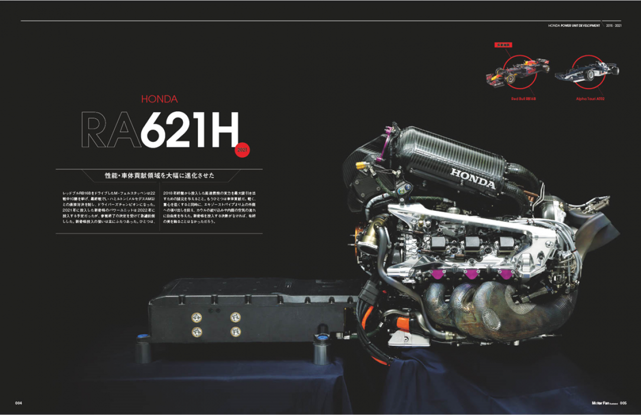
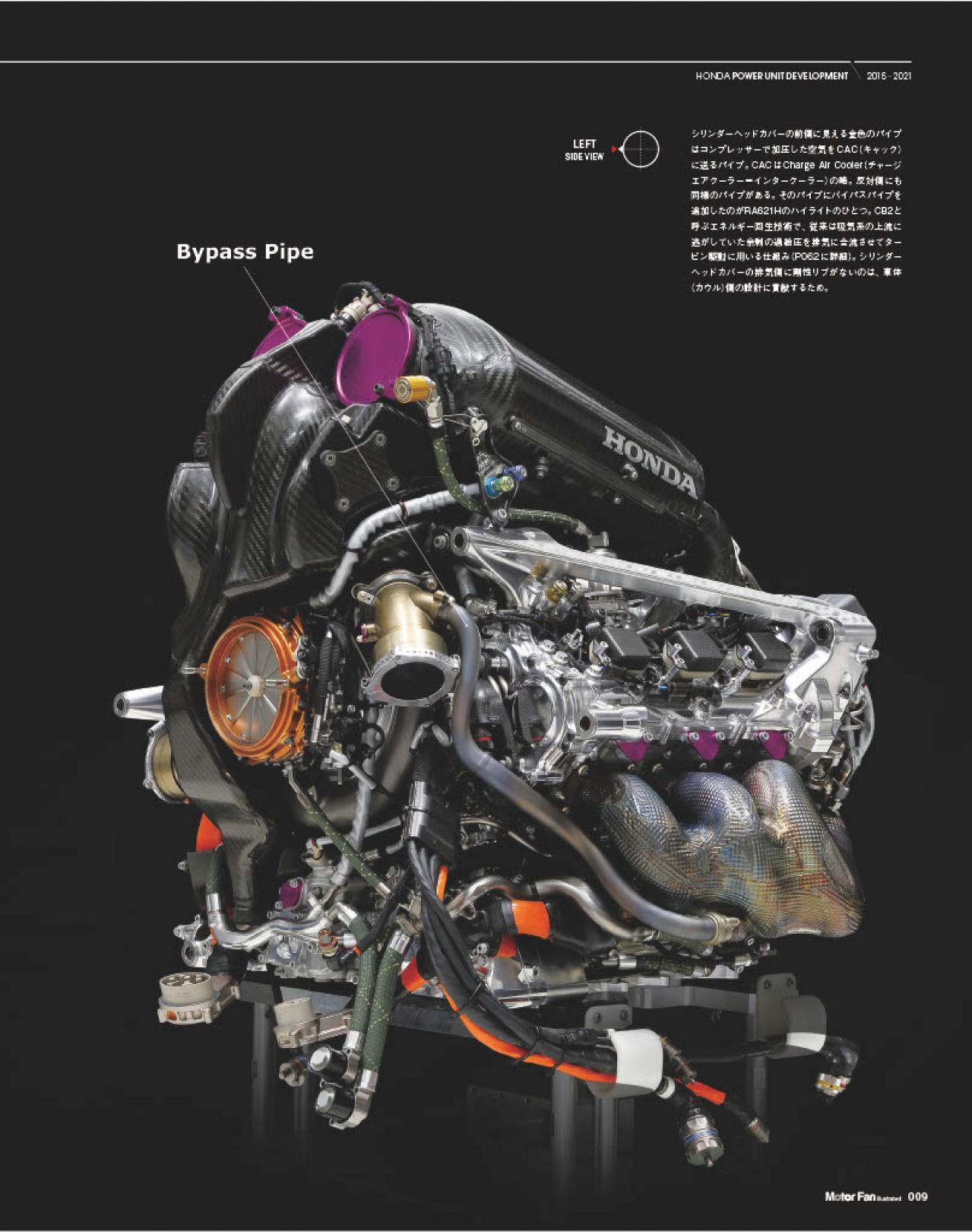
Driving the Red Bull RB16B, Max Verstappen secured 10 wins out of 22 races and clinched the Drivers' Championship after a head-to-head battle with Lewis Hamilton (Mercedes AMG) in the final race. The new power unit architecture, initially planned for introduction in 2022, was brought forward due to the Honda’s decision to withdraw from F1 by the end of 2021 season. There were two main objectives for implementing the new architecture.
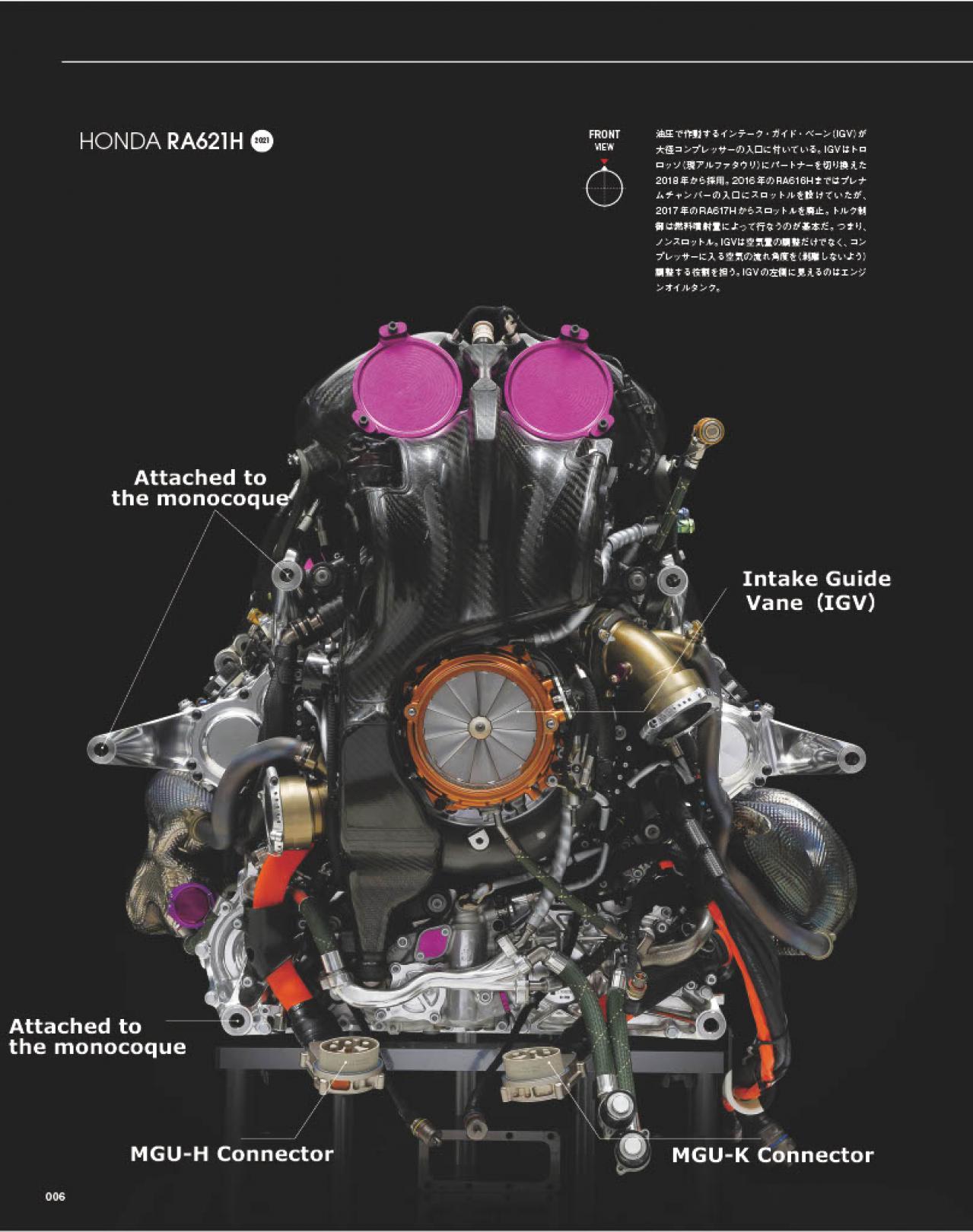
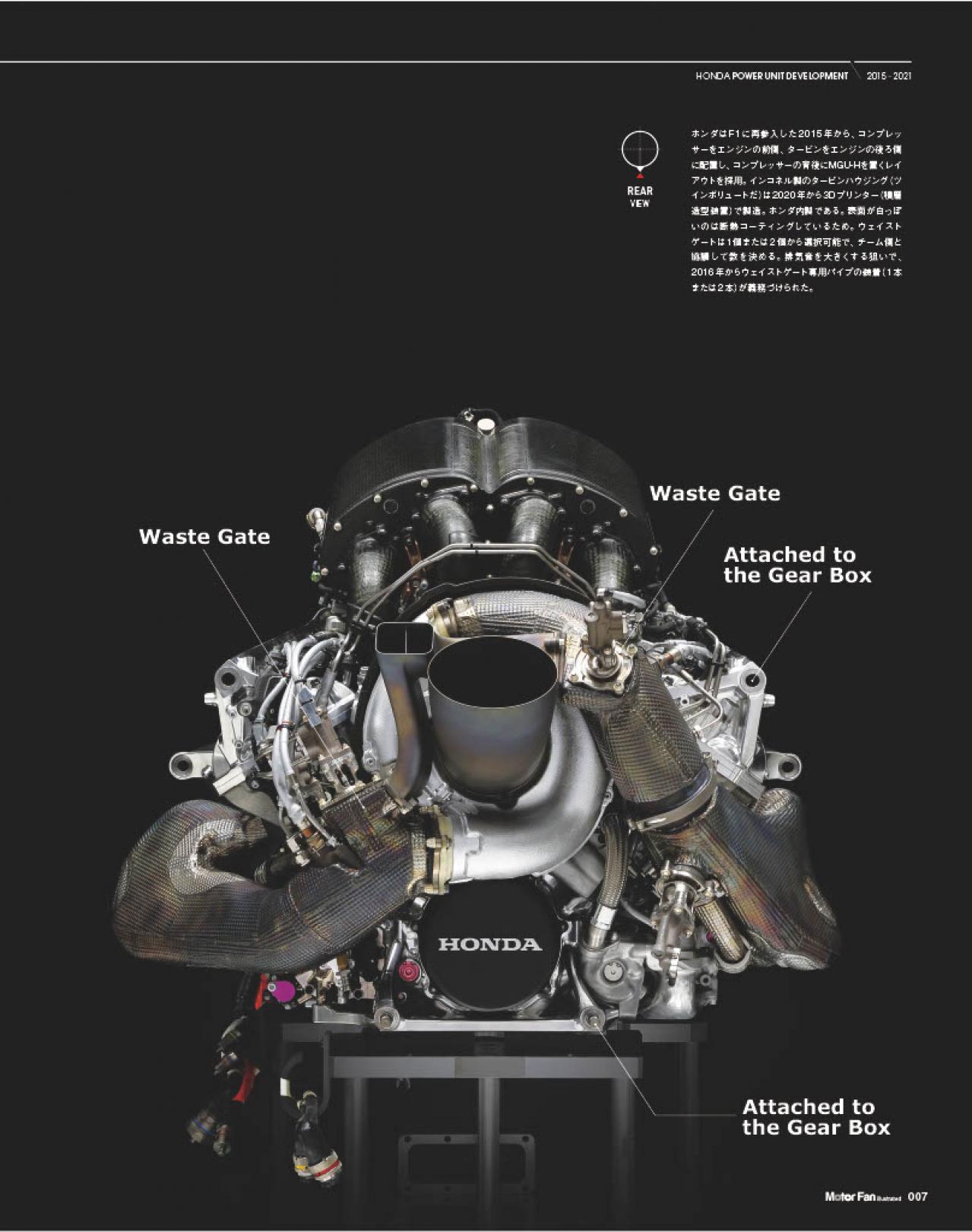
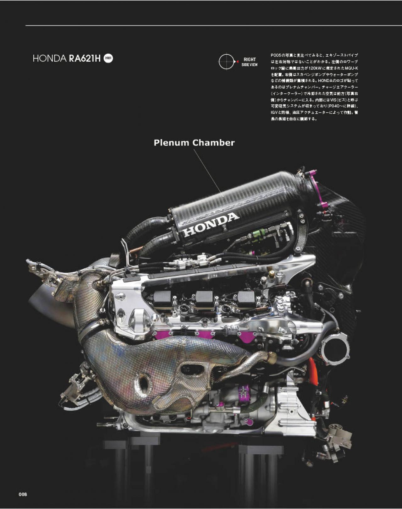
First, to provide specifications that could maximize the performance of the high-speed combustion system introduced in late 2018. Second, to enhance contribution to chassis by making the unit lighter, lowering the center of gravity, and minimizing the protrusion above the exhaust pipes, which allowed for tighter cowl packaging and greater freedom in the flow of air inside. Without the decision to introduce the new architecture, it would have been unlikely to end on such a high note.
Technology for Faster and More Intense Combustion
Honda's ICE development began with "high-tumble combustion," which is an extension of conventional technology. To improve thermal efficiency, the goal was to mix air and fuel well and burn it quickly. By increasing the tumble (a vertical vortex with a horizontal rotation axis), the flame propagation speed increases, leading to faster combustion.
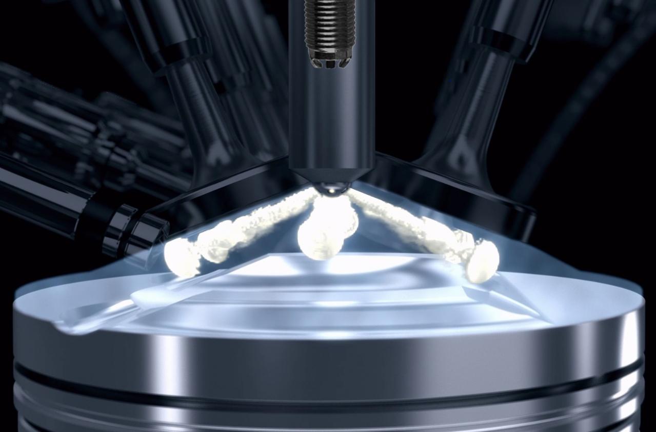
An even faster combustion technology is the "pre-chamber jet ignition" (details to be discussed later). In this method, a small pre-chamber around the spark plug ignites the air-fuel mixture. Jets of flame are ejected from tiny holes in the walls of the pre-chamber, instantly igniting the lean mixture in the main combustion chamber. This technology was fully introduced with the RA617H in 2017.
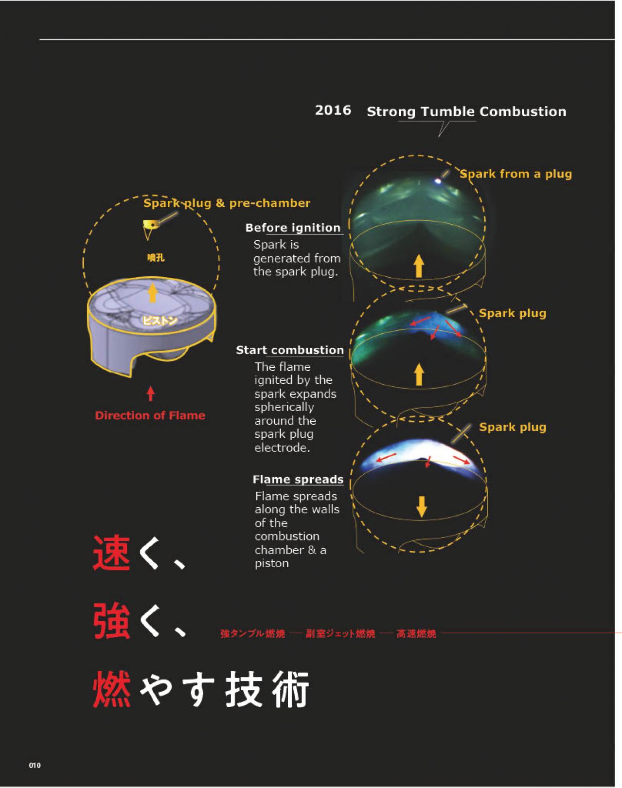
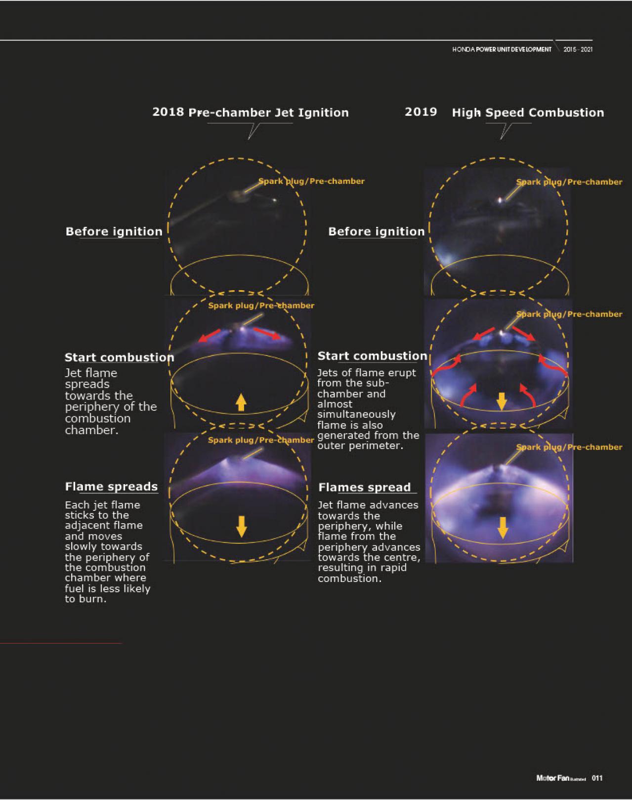
High-speed combustion was applied from the Spec 3 version of the RA618H, which was introduced at the 16th round of the 2018 Russian GP. Whether using high-tumble combustion or pre-chamber jet ignition, the flame propagation still occurs from the central spark plug or pre-chamber outward toward the periphery of the flat-shaped combustion chamber (the maximum bore diameter is regulated to 80mm, and with an 80mm bore, the stroke becomes 53mm).
In high-speed combustion, jets of flame from the pre-chamber act as a trigger, causing auto-ignition at the periphery. Since flame propagation occurs from both the central and peripheral areas, combustion is rapid. Increasing the volumetric ratio promotes auto-ignition, making this method well-suited to high compression ratios.


